

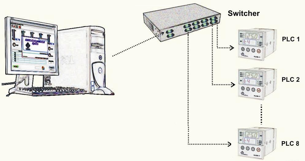
Switcher
If several PLC2B devices are available, it is necessary to connect the cable to the computer for connection to the computer, separated from one device and connected to another. Using the switch allows the user no need to do this. The switch also provides the user with the ability to control the PLC2B devices.
The switch has a RS-232 output port for the computer, eight RS-232 input ports for connecting devices to it, and an RS-232 input port for another switch (if any). In this way, all connections are serial and their cable is directly connected to the cable. On switch 4, the MOD, SEL key is raised and lowered. The switch has two adjustable parameters, which can be entered into the settings by holding the MOD key for 3 seconds. Now, every time you press the MOD button, you can switch between the two Mod and S-n parameters, and then by pushing the SEL key, you can enter any parameter and use the up or down keys to change the corresponding parameter. To exit the settings, you must hold the MOD key for 3 seconds.
In the software after pressing the start button, receiving information from the device, if the switch is used between the computer and the devices, the software will automatically detect it and the window of the device selection will be activated by selecting the desired device number and pressing the OK button of the switch device That device connects.
If a switch is used (the maximum number of PLCs that can be connected to one switch is 8), you must put it in the MSr mode and set the switch number (S-n) to 1. In this case, you must enter numbers 1 through 8 in the software to connect the computer to devices connected to the switch.

If the number of devices is more than 8, we need to use another switch and connect it to the previous switch. In this case, the new switch number (S-n) must be set to 2. To communicate with devices connected to the second switch, you must enter numbers 9 to 16 in connection with the computer. Similarly, if you use a third switch, you have to enter the number 3 in the S-n, and in connection with the computer, select numbers 17 to 24 to connect to the PLCs connected to the switch. In addition, only one of the switches must be set to MSr mode and the rest must be set to SLV mode. Similarly, we can connect up to 8 switches and 64 devices to the computer.

Modem and modem interface
Modem
To connect a remote device to a computer (via a telephone line), you must use a communication device called a modem. By connecting the modem to the device and connecting the telephone line to it, you can access all the features of the device in direct connection mode.
Modem interface
The modem interface device is an intermediate device for connecting modems to hardware devices and allowing them to communicate remotely using a telephone line. To do this, it is necessary to have a computer with a modem (internal or external), a telephone line connection (urban lines or internal lines), an external modem and its associated cable, the corresponding hardware device and cable, and the interface device Modem is provided.
How to communicate:
The modem interface device has a power cable and two connectors for connecting the PLC and the external modem (external). For modem and modem connection, it is better to use the main modem cable itself.
Device display:
The display of the modem interface device consists of two Seven Segments, which in addition to displaying the device’s display, it displays the working status.

1- Connect the external modem cable (external) to the modem interface device (MODEM) first, then turn on the modem and modem interface devices.
2. The device initially displays code 50 and starts writing code 10, 20, 30, and 40 each time. If there is a problem with the modem device (such as not being clear, etc.) or the connection cable is definitive, then the device code 51 shows. After the bug fix, both the modem and modem interface should be turned off and on again. If there is no problem, the device will show code 40.
3. The modem interface interface shows the 99 and 01 codes each time the phone rings.
4. After communicating between the hardware device and the modem interface, a series of information code is displayed, and if the modem interface can correctly establish the connection between the computer and the hardware device, code 22 is displayed.
5. Depending on how to disconnect, one of the codes 36, 44, 33, 83 may be shown, indicating that the connection is interrupted and the modem interface device is waiting for the next call.
In the device software to communicate with the device, we must specify the phone number, passcode and serial number used for the modem, so you must go to the Select Port menu in the Set computer menu and the port number The device is connected to it, enter the passcode and phone number. Therefore, in the software, when the key of communication (Online) is started, the software starts dialing the phone number to connect to the device.

If we want to control the number of devices we want to remotely control from one, we can use a switch device to run this method, connect the devices to the switch and then connect the switch to the modem, then the option to use it is the use switch (In the Select port menu).
Rack
Each rack can include multiple PLC2B devices along with a switch. For example, the following rack includes ten PLC2B devices and two switching devices.
As shown in the figure, rack inputs for temperature and humidity sensors and power supply are 220V. Each of the devices has a separate signal lamp and a separate ON / OFF key.
The signal light for each device represents the status of the alarm for that device.
A serial cable is also provided for communication with the computer behind the rack.